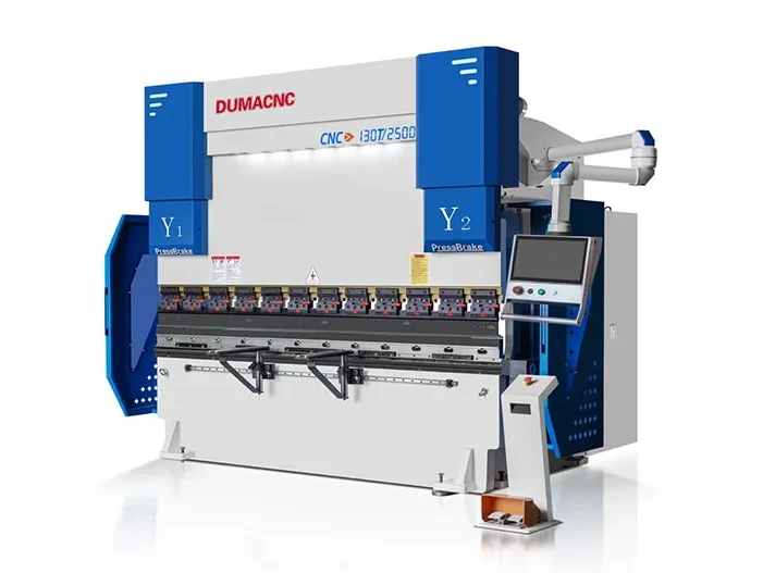

CNC Press Brake 6-8 Axis
- Overall welded and processed structure
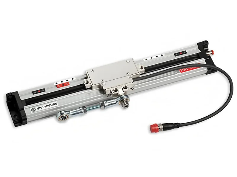
- Closed loop control mode composed of electric-hydraulic servo valve and measure ruler, ensure the highest precision, bending accuracy and repositioning accuracy are also reach the highest level.
- Back gauge mechanism can control several axis.
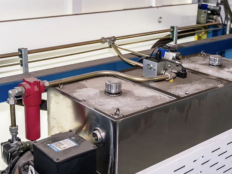
- Integrated hydraulic system decreases the pipe connections, oil leakage and increase the stability and overall reasonable appearance.
- Hydraulic compensation mechanism helps to prevent the deformed slider from affecting the quality of the workpiece and compensation mechanism adjusted automatically by the CNC controller which is convenient and accuracy.
- Controller system adopt Holland Delem, Italy ESA, and Swiss CYBELEC with multi-language selection.
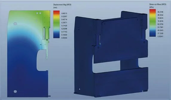
- Important parts such as the fuselage and sliding block are analyzed by ANSYS finite element analysis software to ensure the reliability of the machine tool.
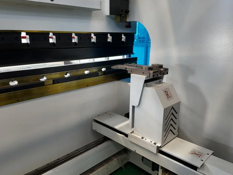
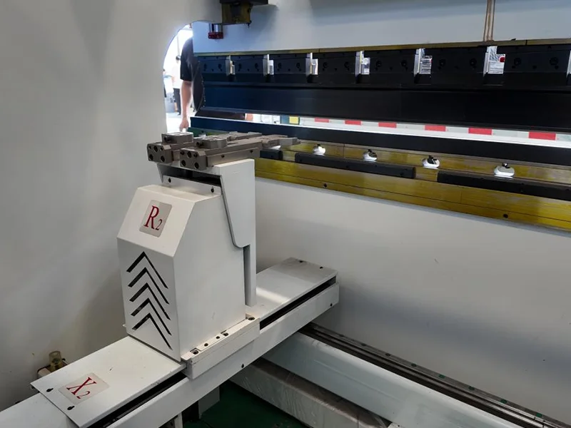
- Using a fully functional backgauge mechanism, which can choose to control multiple backgauge shafts. Functional parts in the backgauge. Such as guide rails, lead screws, bearings, etc., all use imported original parts to ensure the accuracy of the back gauge.
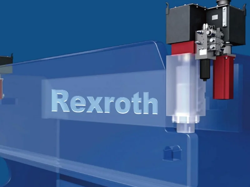
- The hydraulic system adopts the integrated control system imported from Germany, which reduces pipeline installation, improves the working stability of the machine tool, and has a beautiful and simple appearance.
Technical Specifications for 6-8 Axis CNC Press Brake
For more detailed parameters, please don’t hesitate to contact us.
| Machine tool type | Nominal pressure (KN) | Bending length (MM) | Column spacing (MM) | Throat depth (MM) | Cylinder stroke (MM) | Maximum opening height (MM) | Main motor power (KW) | Dimensions (L*W*H)MM |
| 50T/1600 | 500 | 1600 | 1300 | 320 | 150 | 430 | 5.5 | 3000*1400*2300 |
| 70T/2500 | 700 | 2500 | 2000 | 350 | 150 | 430 | 5.5 | 3000*1400*2400 |
| 110T/2500 | 1100 | 2500 | 2000 | 450 | 200 | 500 | 7.5 | 4000*1600*2700 |
| 110T/3200 | 1100 | 3200 | 2700 | 450 | 200 | 500 | 7.5 | 4000*1600*2700 |
| 110T/4100 | 1100 | 4100 | 3600 | 450 | 200 | 500 | 7.5 | 4800*1600*2700 |
| 130T/3200 | 1300 | 3200 | 2700 | 450 | 200 | 500 | 11 | 4000*1600*2700 |
| 130T/4100 | 1300 | 4100 | 3600 | 450 | 200 | 500 | 11 | 4800*1600*2700 |
| 170T/3200 | 1700 | 3200 | 2700 | 450 | 200 | 500 | 11 | 4000*1650*2800 |
| 170T/4100 | 1700 | 4100 | 3600 | 450 | 200 | 500 | 11 | 4800*1650*2800 |
| 170T/6000 | 1700 | 6000 | 5300 | 450 | 200 | 500 | 15 | 6600*1750*2900 |
| 200T/3200 | 2000 | 3200 | 2700 | 450 | 200 | 480 | 15 | 4000*1750*2900 |
| 200T/4000 | 2000 | 4000 | 3500 | 450 | 200 | 480 | 15 | 4800*1750*2900 |
| 200T/6000 | 2000 | 6000 | 5300 | 450 | 200 | 480 | 18.5 | 6600*1850*3450 |
| 250T/3200 | 2500 | 3200 | 2700 | 450 | 250 | 530 | 18.5 | 4000*1850*3100 |
| 250T/4000 | 2500 | 4000 | 3500 | 450 | 250 | 530 | 18.5 | 4800*1850*3100 |
| 250T/6000 | 2500 | 6000 | 5300 | 450 | 250 | 530 | 22 | 6600*1950*3200 |
| 300T/3200 | 3000 | 3200 | 2600 | 450 | 250 | 530 | 22 | 4000*1950*3200 |
| 300T/4000 | 3000 | 4000 | 3400 | 450 | 250 | 530 | 22 | 4800*1950*3400 |
| 300T/6000 | 3000 | 6000 | 5200 | 450 | 250 | 530 | 30 | 6600*2150*3430 |
| 400T/4000 | 4000 | 4000 | 3300 | 450 | 300 | 540 | 30 | 4800*2100*3500 |
| 400T/6000 | 4000 | 6000 | 5100 | 450 | 300 | 540 | 37 | 6600*2300*3700 |
| 500T/4000 | 5000 | 4000 | 3300 | 450 | 300 | 540 | 45 | 4800*2100*3600 |
| 500T/6000 | 5000 | 6000 | 5100 | 450 | 300 | 540 | 45 | 6600*2300*3800 |
Overview of 6-8 Axis CNC Press Brake Configuration
FEA & Stress Analysis
Stress Analysis & Finite Element Analysis.
DUMACNC role of finite element analysis (FEA) for press brakes is to simulate and evaluate the stress, deformation, and performance of the equipment under various operating conditions, thereby optimizing design, improving product quality, and enhancing reliability. FEA enables precise prediction of the strength and rigidity of critical press brake components, identifying potential structural weaknesses, which reduces material waste and cost overruns during the design phase. Its advantages include improved equipment safety and durability, shortened development cycles, reduced costs for physical testing, and support for customized designs to meet specific customer needs. By leveraging FEA, press brake manufacturers can deliver more efficient and reliable products, strengthening their competitive edge in the market.
Standard Equipment
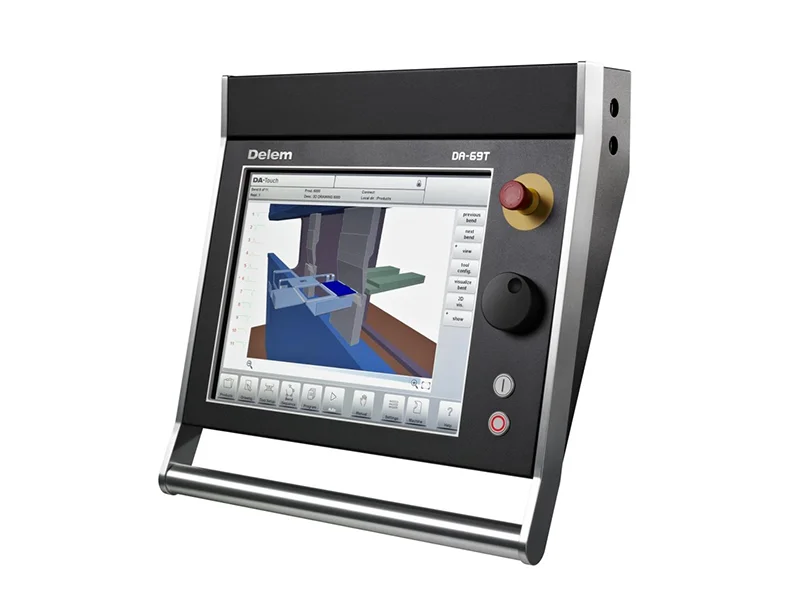
- CNC DELEM DA69T featuring 3D color graphics
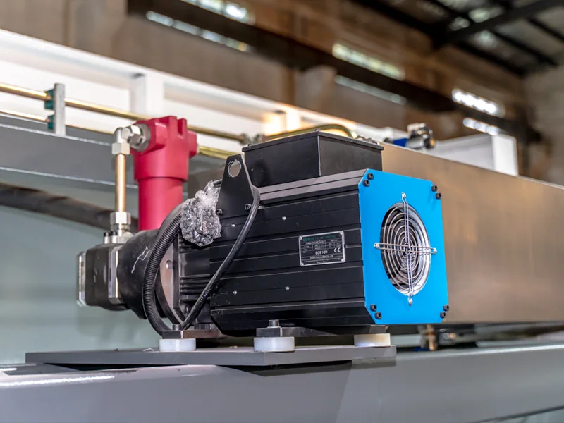
- Main Motor: ESTUN/INOVANVE Main Servo Motor
- Hydraulic System: Bosch-Rexroth (Germany)
- Grating Ruler: GIVI (Italy)
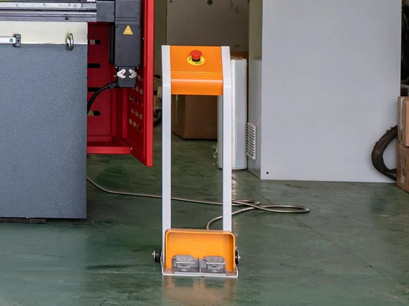
- Foot Pedal: Kakun(Korea)
- Pump: Sunny(USA)
- X, R, Z1, Z2-Axis equipped with HIWIN linear guides and ball screws
- Standard BGA-2 for X and R axes (X=600mm, R=200mm)
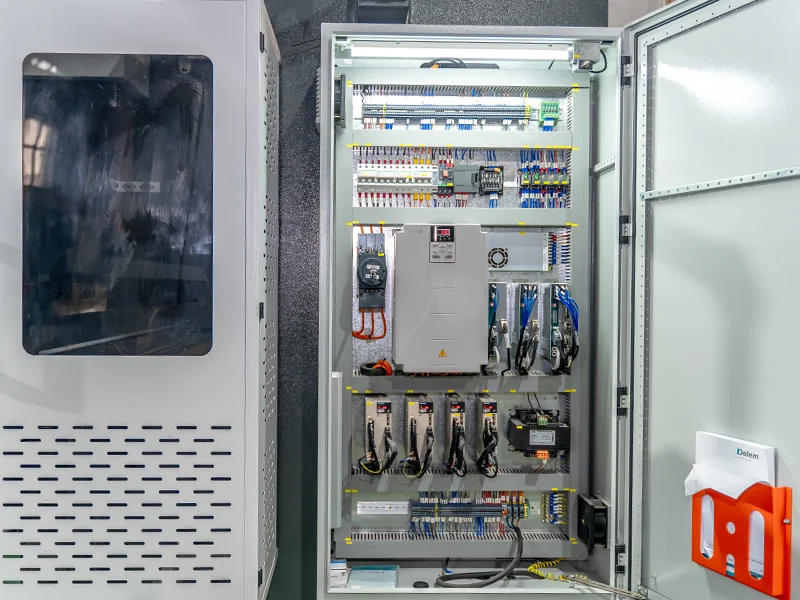
- Electrical Components: Schneider (France)
Introduction to Configuration of CNC Press Brake 6-8 Axis
DA-69T Features:
The DELEM DA-69T provides both 2D and 3D programming, featuring automated bend sequence computation and collision detection. It supports comprehensive 3D machine configuration with multiple tool stations, delivering accurate feedback on product feasibility and handling.
17″ high resolution colour TFT
2D graphical touch screen programming mode
3D visualisation in simulation and production
Delem Modusys compatibility (module scalability and adaptivity)
USB, peripheral interfacing
Profile-T2D offline software
Sensor bending & correction interface
CNC Control System
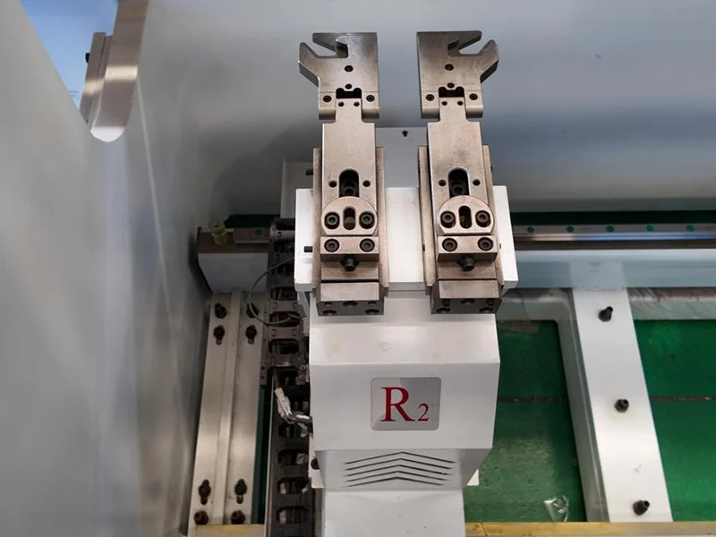
BGA-6 BackGauge


Backgauge Features
X and R axes equipped with ball screws and linear guides
Z1 and Z2 axes feature precision linear guides and YYC rack system
Dual-stop fingers with micrometric adjustment
Mechanical precision of ±0.03 mm
R1-R2 axis speed: 500 mm/s
X1-X2 axis speed: 600 mm/s (optional 1000 mm/s)
Z1-Z2 axis speed: 1100 mm/s
Want to get the price of our CNC press brake 6-8 Axis?
Get in touch with our team of experts to receive professional suggestions.
Products Details
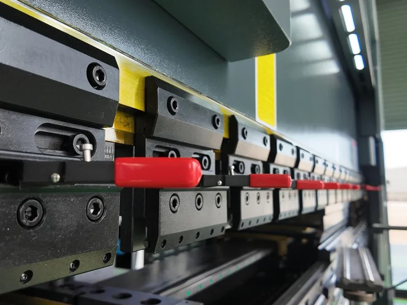
Fast Clamping
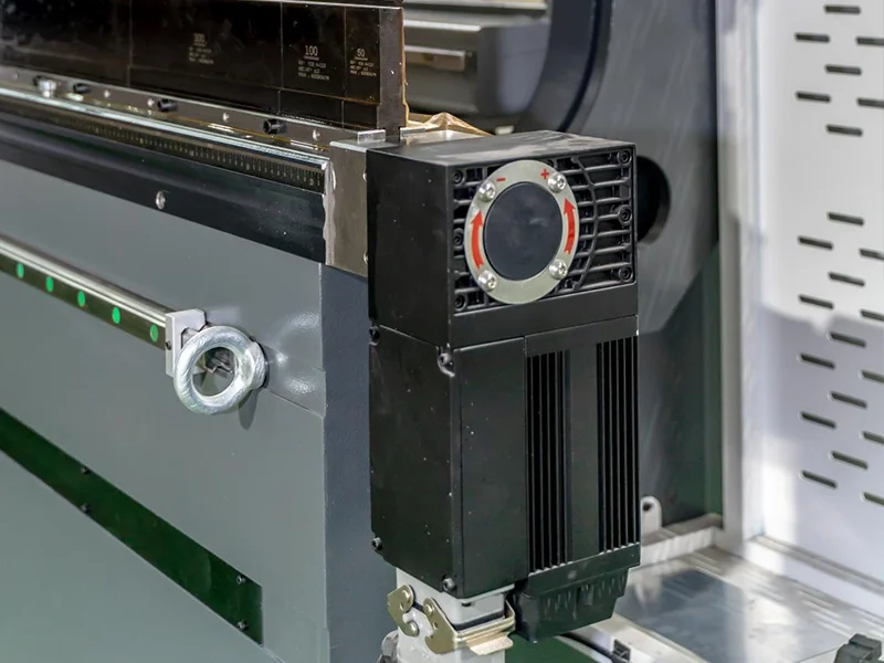
Deflection Compensation
The compensation amount is automatically calculated and set by the numerical control system to ensure the consistency of the full-length bending angle.
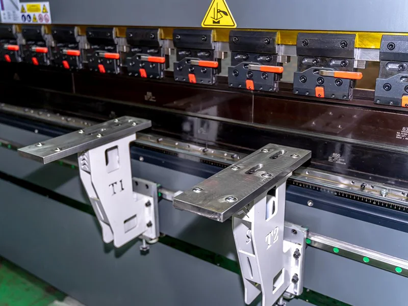
Front Plate Support
Advanced Multi-Axis Back Gauge
Hydraulic System--German Rexroth valve
ESTUN/INOVANCE SERVO Motor
Grating Ruler
KAKUN Korea Pedal switch
Hybrid Servo System
Schneider Electric
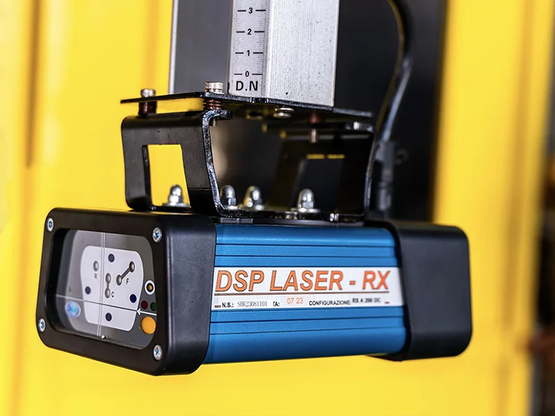
Laser Protection Features:
The bending machine laser protection device is divided into two parts :detection system and system The detection system includes transmitter,receiver,signal transmission line,mounting bracket,etc.
Light source has small divergence and is resistant to reflection interference.
Suitable for fat bending, box bending,Z-bending and other workpieces.
Efectively preven taccidental crushing during bending.
The chip judgment data can be automatically aligned during bending vibration.
Protection grade: IP65.
Protection range:20m.
Induction mode: opposite shooting.
Response time:15s. Sensing distance:0-3m CE certification.
Laser Protection
Laser Angle Detection
Laser Angle Detection Features
On line detection of metal bending-easy integration and cost-effective.
Laser-based Bending Angle Measurement System
Innovative sensors for measuring bending angles on press brakes
Easy to Use Parallel use 2 of 4 sensor
Spring-back calculation by using for detection withstrain gauges or by detecting the end of angle variation
Connection to ESA Cvbelec, Delem, Amada, Robosoft controls and others High Accuracy
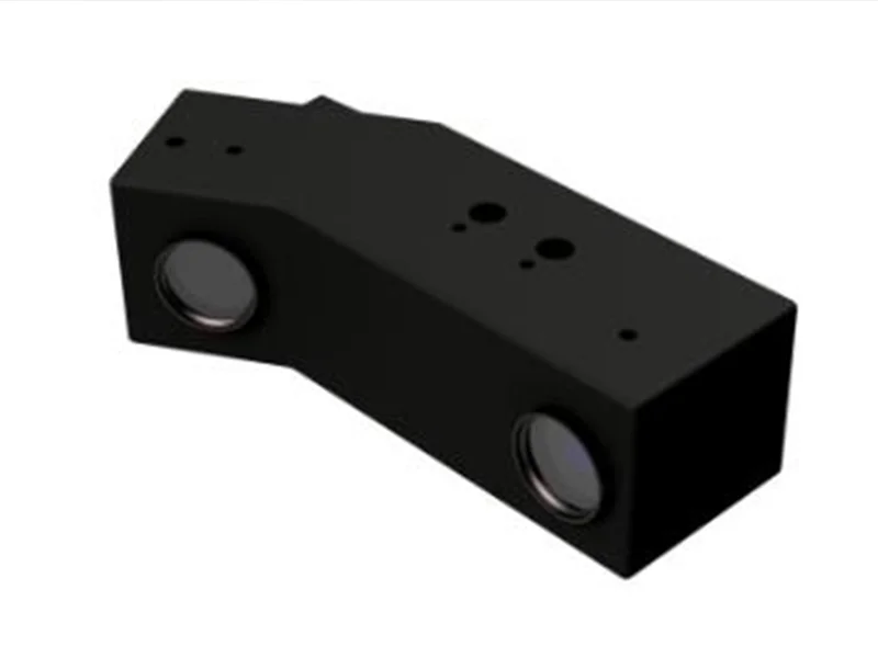
He Laser Check sensor is mounted on the press brake, below the die, With an angle of 35°-55°to the vertical.
The working distance (between sensor and sheet) is90-2000mm, Depending on the sensor type.
It is move able along the die either manually or automatically.
Due to its mounting position the measuring range is30°-180° (bending angle).
For each measuring position 2 sensors are used.
Motorized sensors enable an independent correction of the beam to Compensate angle differences in long bends.
Measurement in the machine center allows crowning correction (depending to the control).

Fill in the form below and our team will be happy to assist you!